Plastic injection molding is a manufacturing process wherein plastic is injected into aluminum, or steel molds and squeezed under high pressure to come up with the desired shape of the product. The molding material is heated so that it comes in a fluid state and is injected into a mold until it hardens. The product is usually designed by industrial engineers or designers. Injection molding is mostly used for manufacturing very small to very big items or parts of cars.
There are a number of companies offering as StarMould. Companies sell either newly used molds or injection molds.
Customers have varying levels of knowledge with regards to plastic injection molding. They come up with product designs and the molding companies manufacture the injection mold tool to make the plastic parts.
Here are the basic plastic injection key terms that you should know regardless of your level of knowledge on plastic injection molding to be able to describe your ideas to industrial designers or engineers so that they can design and transform them into exactly how you imagine your molds to be.
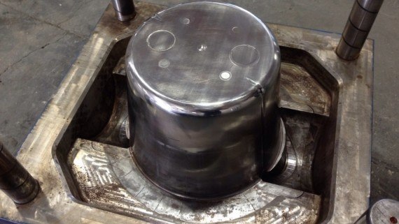
- Cavity – This is the concave or depression in a plastics-forming mold which usually forms the outer surface of the molded part. The molds can be designated as either single cavity or multi-cavity according to the number of depressions.
- Core – This is a projection or a set of projections in a plastics-forming mold that forms the inner surface of the mold. This is a channel in the mold used for circulation of a heat-transfer medium.
- Draft or Draft Angle – This is the degree or angle of taper in a side wall designed to facilitate the removal of the parts from the mold.
- Flash – Excess plastic material that is outside a seam or attached to a mold parting line which is not intended to be there. It is generally caused by mold damage, improper mold design, and/or poor clamping. This is unacceptable in most cases and should therefore be removed before the parts are deemed acceptable.
- Gate – A channel through which the molten liquid plastic flows into the mold cavity. The remnants of plastic left over from the gate area can be trimmed once the part is ejected. There are two kinds of gates:
- Automatically Trimmed Gates: They integrate features in the tool to stop the gate while the molding tool is opened to remove the part.
- Manually Trimmed Gates: They need an operator to separate parts from runners during a secondary operation.
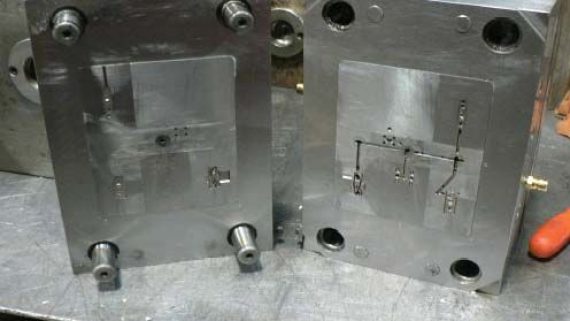
- Line of Draw – The point or direction wherein the two molding halves separate to show the injection molded part.
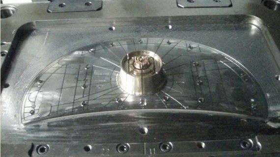
- Runner – The feed channel that connects the sprue with the cavity gate for transporting the melted material to the cavities. The melted material travels from the sprue, to the runner, to the gate, and into the cavities.
- Shrink Rate – The rate at which the molded part will shrink once it is cooled which ranges from 0.001-0.060 per inch.
- Sprue – The opening connecting the runner to the nozzle of the injection molding machine.
- Warp – The dimensional distortion during cooling or molding that is caused by internal stresses such as uneven material flow, un-uniform wall selections, cooling, and compression.